


In my graduate work, I draw a lot of system diagrams which basically involves drawing a bunch of shapes with arrows. When typesetting my figures, I like using the Pic preprocessor because of its expressiveness. In the following post I will show how to use it.
This article is an updated version of a post from my personal blog.
Take a look at the code below:
 .PS
 A: circle  "A"
 line right then down
 B: circle with .n at Here
 line -> from A.s to B.w
 .PE
This will generate the following figure:
Below is my workflow when writing Pic diagrams:
- Install the Pic preprocessor. Most *nix distributions come with the GNU pic along with the groff-related packages. For a more powerful preprocessor, I recommend J. Aplevich’s Dpic. It supports preprocessing to other LaTeX graphics libraries such as PSTricks and TiKz. Here we compile the above code using GNU pic:
$ cat figure.pic | pic -t > figure.tex - Pic is a preprocessor and compiles any code in between the .PS and .PE. Although in principle you can embed them directly in your LaTeX documents, most people practice placing their Pic figures in a separate file.
- Embed the generated LaTeX file in your document. The GNU
pic(1)manual recommends embedding your latex in a specific way:
 \input{figure.tex}
\box\graph - Compile your LaTeX code as you normally would.
My first encounter with Pic was when I was looking for ways to typeset my Electrical Engineering reports during undergrad. That time, I found the Circuit_macros package, also by J. Aplevich. Circuit_macros provides a set of M4 macros to draw circuit components. Using it is the same as working with normal Pic figures but you have to pre-process the figures through m4 first.
$ cat figure.m4pic | m4 -I ./circuit_macros | pic -t > figure.tex
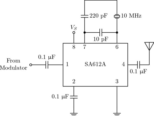
Here is an example figure I made during my undergraduate year:
 .PS
 include(libcct.m4)
 cct_init
# Usual defs...
qrt=dimen_/4;
hlf=dimen_/2;
dim=dimen_;
mm=1/25.4;
pi=atan2(0,-1);IC: box ht 2*dim wid 3*dim "SA612A"
In: capacitor(left_ at IC.w hlf); rlabel(,0.1~\micro\farad,)
circle rad 0.025 fill 0 with .c at In.end
box invis wid 1.5*dim "From" "Modulator" with .e at last circle .w
move to IC.w "1" then right 0.1move to IC.nw+(2*qrt,0) "8" then down 0.1
move to IC.nw+(2*qrt,0); line up hlf; circle rad 0.025 fill 0 with .c at Here; "$V_S$" abovemove to IC.nw+(4*qrt,0) "7" then down 0.1
move to IC.nw+(4*qrt,0); line up hlf;
Junc1: dotmove to IC.ne-(2*qrt,0) "6" then down 0.1
move to IC.ne-(2*qrt,0); line up hlf;
Junc2: dotcapacitor(from Junc1 to Junc2); llabel(,10~\pico\farad,)
capacitor(from Junc1 up_ 1.5*dim); rlabel(,220~\pico\farad,)
line to (Junc2.x,Here.y)
xtal(from Junc2 up_ 1.5*dim); rlabel(,10~\mega\hertz,)move to IC.sw+(2*qrt,0) "2" then up 0.1
move to IC.sw+(2*qrt,0); capacitor(down_ dim); rlabel(,0.1~\micro\farad,); groundmove to IC.se-(2*qrt,0) "3" then up 0.1
move to IC.se-(2*qrt,0); line down dim; groundmove to IC.e "4" then left 0.1
move to IC.e; capacitor(right_ dim); rlabel(,0.1~\micro\farad,)
line up hlf; antenna(,,T)
There are a lot of better resources on GNU pic/ Dpic and Circuit_macros than this introductory post:
- In Praise of Pic – O’Reilly media’s detailed introduction to the language.
- PIC – a language for typesetting graphics – Tech Report about the language by B. Kernigham, the original author of Pic.
- Draft Dpic manual – by J. Aplevich.
- M4 Circuit_macros – Getting Started – Good introductory article by P. Randewijk
- CMman – the Circuit_macros manual by J. Aplevich.